021-39529839
电 话:021-39526589-8004
联系人:冯娇
手 机:17316599802
地 址: 中国 上海 嘉定区嘉涌路99弄6号713

更新时间:2026-05-29 浏览数:24
所属行业:电工电气> 开关(电工电气)> 流量开关
发货地址:其他
产品规格:--
产品数量:1
包装说明:--
单 价:面议
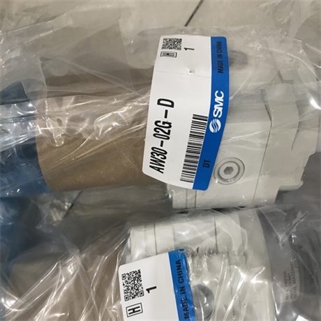
日本SMC膜片式流量开关产品介绍
上海乾拓贸易有限公司
电话:-8004
手机:(微信)
邮箱:@163.com
企业QQ:2880626084
联系人:杨江玲
地址:上海嘉定区嘉涌路99弄6号楼713室
To adjust flow, remove grommet of the upper cover and rotate flow adjusting gear using a flat head screwdriver.
Turning clockwise can increase the set flow and turning counterclock can decrease the set flow.
Body material in contact with fluid material
that corresponds to approximately 5 times the bore of the pipe before and after the area of the pipe on
Water resistance Operating pressure
Liquid flow creates a pressure differential nearby the orifice of the port of the body q.
One set of diaphragms monitors the pressure differential and operates the micro switch through the rod w and operating lever r.
The rod w moves downward with increased flow, and upward with decreased flow.
Moving the gear t upward or downward by the adjusting gear e manually offers an electric signal at various flow rates.
Mount a switch, so that the liquid flow is in the same direction as that of the arrow on the body.
2. The flow switch can be installed either horizontally or vertically. 3. Provide a straight pipe portion
with the fluctuation of the operating flow rate, set the difference between the set flow rate
Operation Insulation resistance Withstand voltage
1500 VAC for one min. Without terminal box: 1ab With terminal box: 1a or 1b 3/8, 1/2, 3/4
Rod Body Diaphragm
or diaphragm damage caused by debris or cutting chips in the fluid, install a filter with approximately 100 mesh on the inlet side of a flow switch.
Water/Non-corrosive liquid ? 0.1 to 0.6 MPa 1.2 MPa –5 to 60°C (No freezing) Diaphragm style 100 MΩ (500 DC by megameter)
which the product is installed, thus keeping the product as far away as possible
from the elements that disturb the flow, such as elbows or valves. 4. For wiring, refer to the internal wiring diagram.
5. If a terminal box is not available, wire by selecting the contact at 1a or 1b.
At that time, insulate the lead wires that will not be used. 6. Because this is an open style, it cannot be used where water or oil splashes.
7. It cannot be used if a water hammer or pulsation pressure is applied to the fluid. 8. In order to prevent a malfunction
2. The flow rate setting point is set at the ON flow rate. Therefore, in the case of the 1a contact,
and the operating flow rate so that it is as large as possible. 4. Use at or below the maximum operating pressure
and maximum flow rate. 5. The indicator on the window name plate (Fig. 1) is only a guideline.
For precise setting, mount a flow meter on the downstream side of the flow switch, and set the level. Also,
when setting levels with a low flow rate at pressures of 0.2 MPa or more, there may be interference
between the indicator needle and the scale plate. In such cases, detach the indicator needle and scale plate before setting.
After setting, the indicator needle and scale plate can be reattached in positions of your choice.
Operating temperature range
the ON signal is output if fluid with a higher flow rate than the set flow rate has occurred.
In the case of the 1b contact, the ON signal is output when the flow rate has decreased
from the set flow rate for the amount that corresponds to the hysteresis. 3. To prevent the chattering that is associated日本SMC膜片式流量开关产品介绍
您是第33541874位访客
公司主营:德国SICK传感器,FESTO比例阀,德国FESTO电磁阀,ASCO电磁阀,NORGREN电磁阀,LEUZE传感器,CKD电磁阀,CKD气缸 沪ICP备09006758号-10
乾拓贸易是销售气缸,继电器的公司,以SMC气缸,PILZ继电器,FESTO气缸为主,产品型号规格齐全,报价合理,可满足不同客户的需求!
版权所有:上海乾拓贸易有限公司